The best think is only replace bios and memory flash by 3.3V chip.
My Dreamcast WORK perfectly with genuine Power Supply, and no bug or other think with this method.
I understand this mod is not easy to do, but this method is simply the best thing.
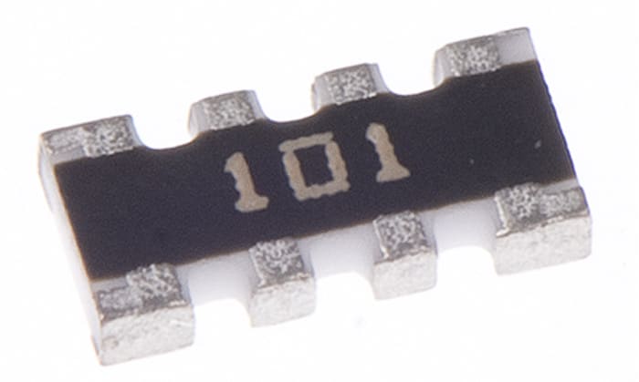
The resistor replacement is something that works, but seen with an electronic eye is something that looks like bad think...
All information is at the top of this topic
")
Dreamcast Service manual is the best reference, and it's say the bus need only 3.3 logic level for VA1 (VS 5V for VA0). Ofcourse, Holy is 5V tolerance and is on VA1 and VA0
Series resistors in line with 3.3V flash parts (such as the Krikzz Everdrive M2 product) is BAD engineering.
The maximum Vin those parts can handle is 4V, after that, all excess votlage is converted to latch-up current by the input clamping diodes - and also means that your console is sourcing alot of current on the data and address lines.
Conclusion : the resistor array swap work but is not the good think. It's work for how many time before burn your GDEMU 3.3V on 5V logic level on your VA0 ?
If imporant to know : The GDEMU on VAO don't burn immediatly, it's work sometime with no modification, but it will dead after some time...
The resistor array reducing current,
but 5V is 5V.
Is not good to compare this method with Evcerdrive MD2 (with cpld MAX2) with resistor array
MAX2 Cpld on Everdrive MD2 cartridge have diode clamp on I/O.
Cylcone too, but you can check on the new Everdrive, krikzz have add logic level transceiver on her new everdrive with FPGA Cyclone and he have delete the series resistors
This is the doc of Altera MAX2 for this :

Regards,
Xrider